
How to Build a Simple DIY Still Air Box/Glove Box
This still air box functions perfectly for common microbiology procedures, such as preparing slants and liquid cultures for Penicillium from a colonized agar plate. It allows for easy use of common tools such as an alcohol lamp, inoculation loop, scalpel, syringe, screw cap culture tube, beaker, and agar plate under sterile conditions. The box can be easily pre-sterilized with isopropyl alcohol, liquid disinfectants, bleach, or UV light. Then it can be used to make yeast cultures for brewing, to inoculate substrate for mycology, or to carry out any other suitable experiments.
Overview and scope:
This tutorial will show you how to create your own still air box/glove box for under $100 using widely available parts purchased from most hardware stores. Having a still air box gives the amateur scientist the ability to perform simple microbiology experiments without the risk of contamination by airborne particles, bacteria, or yeasts. This still air box can also be adapted with an optional vacuum outlet valve and nitrogen/argon gas inlet valve for the dual purpose of being used as a glove box for chemistry. This allows the investigator to handle air-sensitive chemicals safely, preventing degradation of the chemical compound using an inert atmosphere. This may include bottling and storing air-sensitive compounds and even performing safe and simple chemical reactions in the glove box on a small scale, mitigating the risk of the reaction failing due to the presence of oxygen and resulting side products due to oxidation/degradation of the chemical species during the reaction. There are many alternative methods to perform air-free chemistry manipulations and procedures, but these will be discussed in later posts and can be found online and in many advanced laboratory technique manuals.


Parts list:
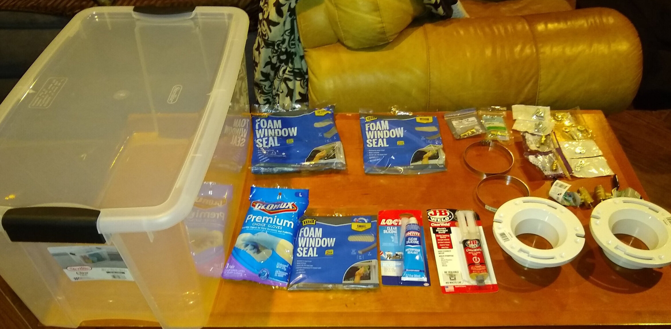
Tote bin of your choice (we purchased a Sterilite Ultra Latch 70 Qt.) - Preferably with the clearest plastic available for visibility. It should also be just large enough that one may be able to move the gloves around all areas of the box for maximum mobility and ease of use. To find the proper size, place your arms out, with your elbows bent at a 90 degree angle in a natural, resting position and measure the relative distance between your arms and the length of your arm, from elbow to fingertip. You can use technique to place your arms over a box or tote bin to get a general idea if it has the proper dimensions for your arm size.
Clorox Premium Choice Gloves (Neoprene Dipped) 13” length - You can chose other types or brands of gloves that work, but generally look for 13” length gloves made of chemical resistant materials, which are solid and non-porous to maintain a pressure seal, allow easy cleaning and sterilization, and prevent contamination.
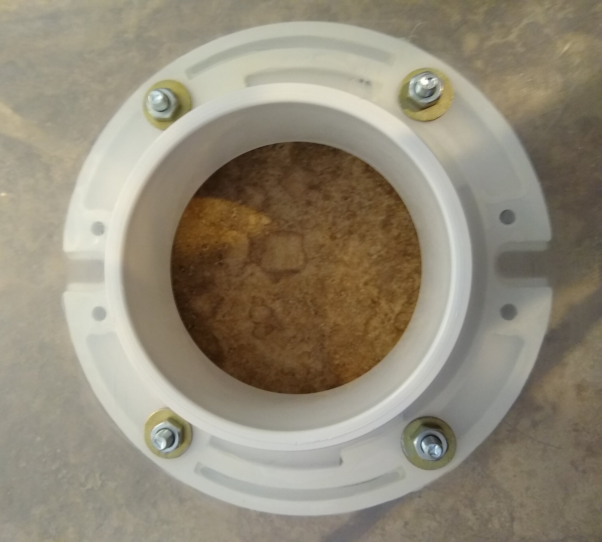
2 x Oatey Fast Set 3" x 4" White PVC Open Hub Toilet Flange - Inner diameter is 4”, which is recommended to fit most arm sizes comfortably. 3” diameter openings are a bit too small for most arm sizes.
2 x 4” diameter adjustable pipe clamps
8 x 1/4-28 x 1” grade 5 SAE hex cap screws
8 x 1/4-28” fine threaded hex nut bolts
8 x 1/4” hardened flat washers USS
JB Weld Clear Weld Quick-Setting Epoxy (or other similar quick-setting epoxy for plastic)
Loctite Clear Silicone Waterproof Sealant (or other similar silicone sealant)
Foam window seal (3/16” x 3/8” x 17’)
4 x 1/2” SAE flat washers hardened (optional)
2 x (12.37 x 2.62mm) viton o-rings (optional)
2 x 1/4” lead free brass ball valve female NPT x female NPT (optional)
2 x 1/4” MIP x 1/4” MIP hex nipple (optional)
2 x 1/4” FIP x 1/4” FIP coupling (optional)
1/4” ID x 1/4” MIP hose barb adapter for inert gas inlet (optional)
3/8” barb x 1/4” MIP hose barb adapter for vacuum pump outlet (optional)

Instructions:
First you must determine where the holes for the glove ports should be placed based on the natural posture of your arms. For me, this was about 14” apart with arms naturally rested and elbows bent at a 90 degree angle. A measuring tape was used to find the center of the tote bin and a line was drawn across the center of the tote bin. Marks were placed 14” apart on the center line with equal distance on both sides of the tote bin to ensure the glove ports would be installed symmetrically.
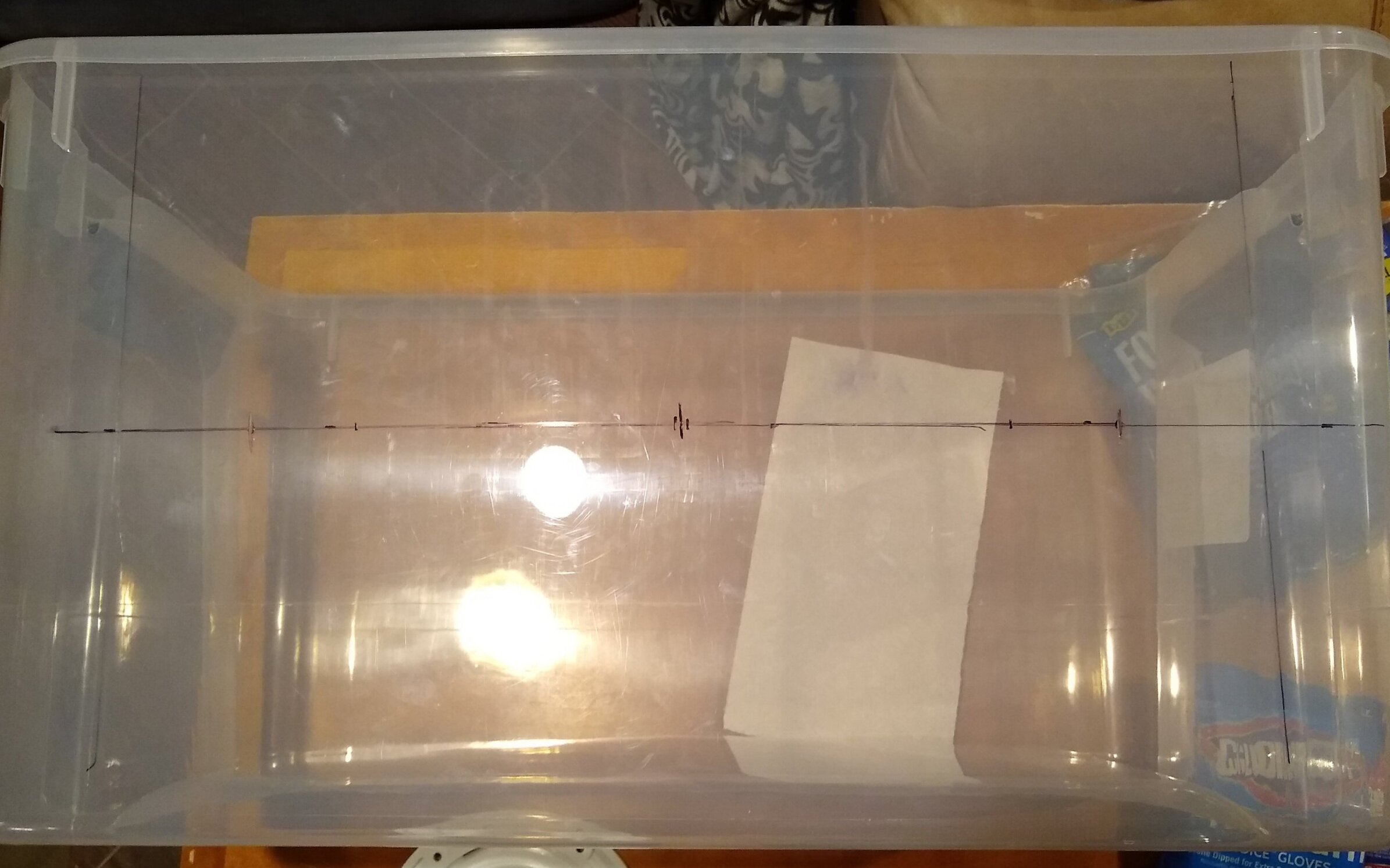
A 4” hole saw was used to drill out 4” diameter holes in the marked areas for the glove ports. The flanges were then placed carefully into the holes to make sure they fit. The flanges fit perfectly and were flush with the tote bin, therefore a marker was used to mark out the 1/4” holes to be drilled to secure the flanges onto the tote bin. Eight holes were carefully drilled using a 1/4” drill bit in the marked locations. The 4” hole and surrounding areas were lightly filed to remove any burrs around the hole and then the entire area where the flange was to be glued was lightly sanded. The entire area was then wiped thoroughly with isopropyl alcohol to remove any marker and unwanted particles.


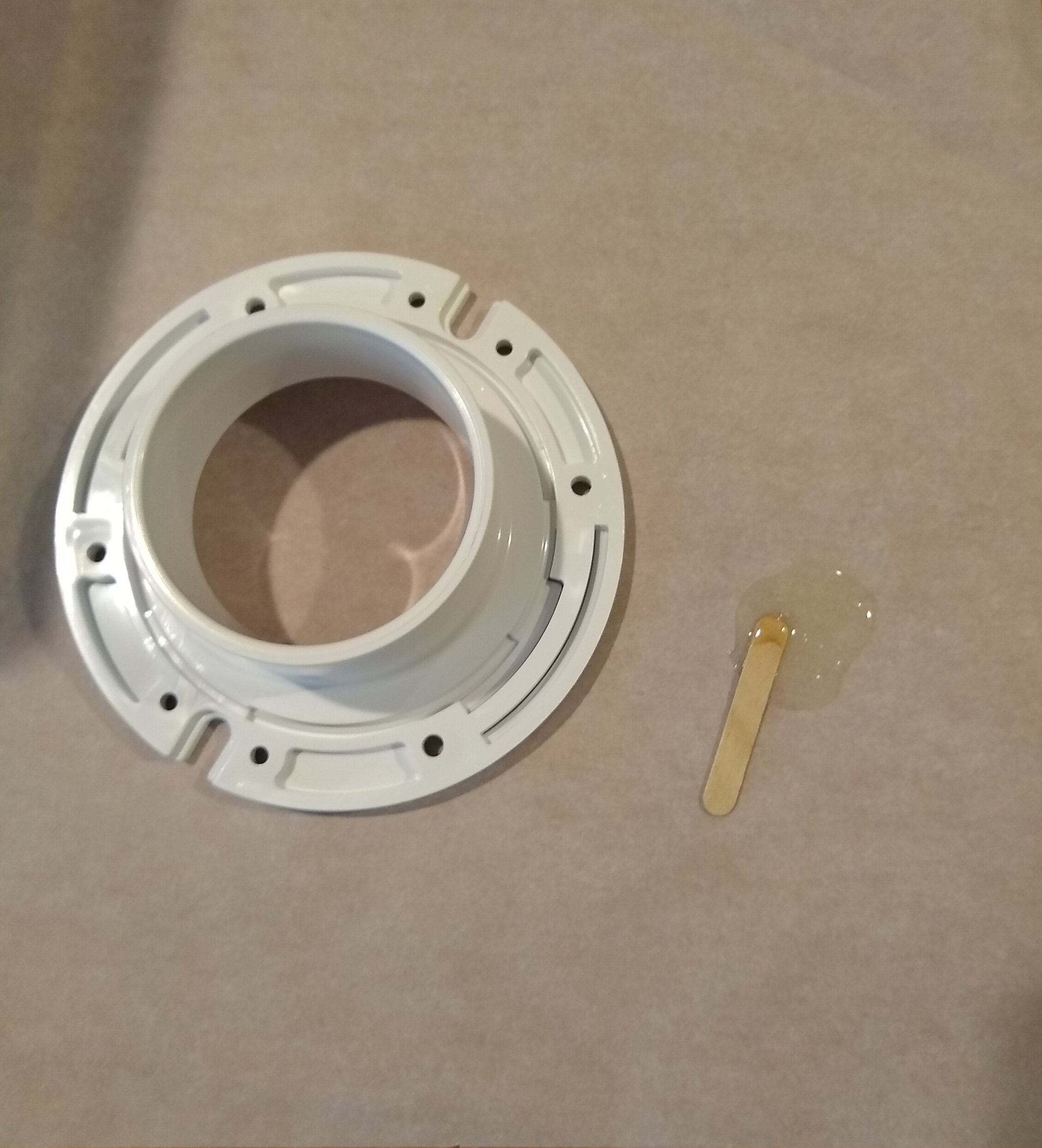
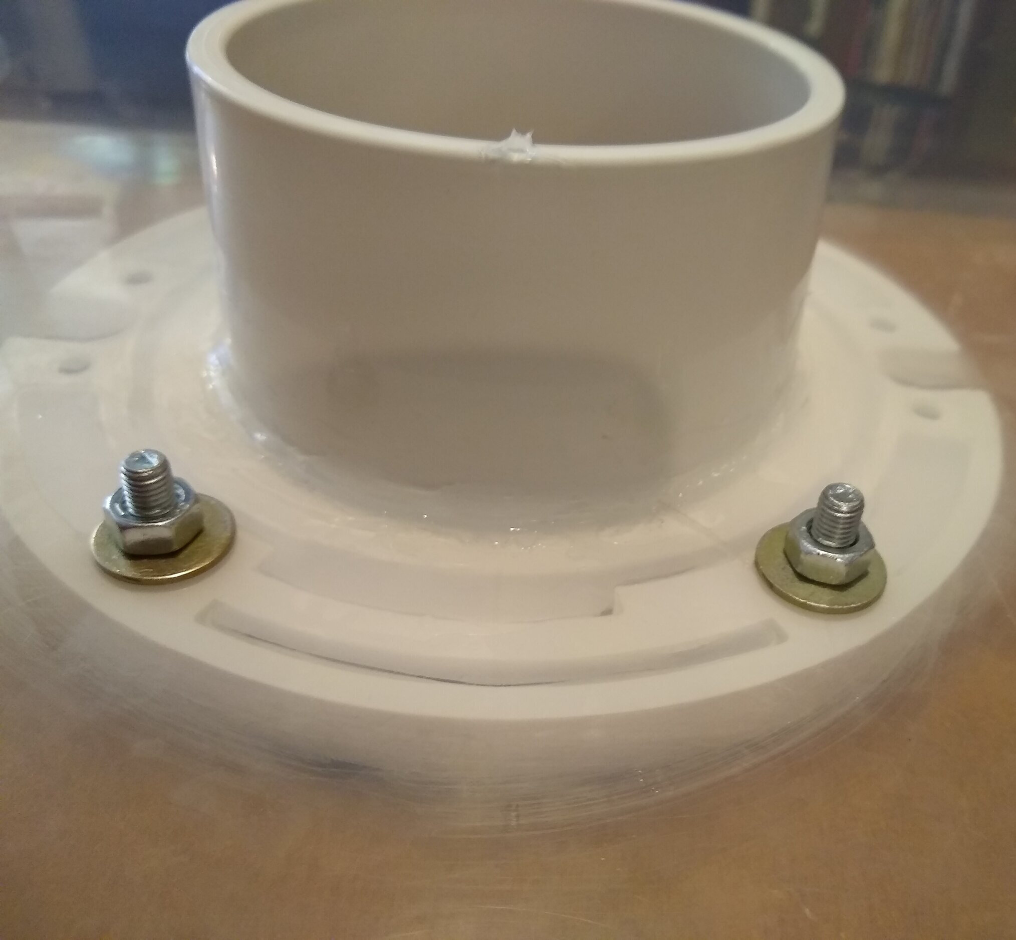
All areas of the PVC flanges were washed with soap and water, dried, and then wiped down with isopropyl alcohol to make the surface smooth and properly adhere to the tote bin with the epoxy. A sheet of parchment paper was placed on the working surface to use to mix the quick drying epoxy. An aliquot of the epoxy was squeezed onto the parchment paper and mixed with the provided wooden popsicle stick by rapidly whipping it. The epoxy was thoroughly applied to the side of the flange that were to be glued to the plastic of the tote bin and evenly spread across the surface of the flange. The flange was then carefully placed into the 4” hole, carfully lining up the the pre-drilled 1/4” holes on the tote bin with the holes in the flange and pressed firmly against the plastic of the tote bin. The 1/4” bolts were quickly placed through the holes and secured by adding the washers and nuts to the threading of the bolts inside of the tote bin. Secure each bolt by hand tightening the nuts, then tighten all the nuts using a wrench. Repeat this same procedure for the second flange. Place the tote bin down, with the outside of the flanges on a flat surface to ensure proper binding of the flanges to the tote bin while the epoxy cures. Let the epoxy cure for at least one hour, but give additional time to cure if the temperature is below 40 °F.


After the epoxy has cured and the flange is tightly bound to the tote bin, waterproof silicone was used to create an air-tight seal between the flange and plastic. Take into consideration that the silicone sealant used should be resistant to any chemicals used to sanitize the still air box for aseptic usage, such as isopropyl alcohol, bleach, and other solvents or water based disinfectants. Loctite waterproof clear silicone was used to ensure a proper seal, although any appropriate silicone sealant can be used. Follow the instructions on the silicone sealant and cut the tip of the applicator to apply the appropriate sized bead of silicone. Slowly begin applying the silicone sealant around the inside edges of the area between the flange and the plastic bin, observing carefully that the silicone sealant is filling any gaps or open areas between the flange and plastic. Make sure to evenly apply a sufficient amount of sealant around the flange and plastic to create a strong seal. Take your time during the process and be careful not to stress or twist the tote bin, as the epoxy may still be curing. Repeat the same procedure on the outside of the tote bin, around the outside edges of the flange. This may not be necessary if the epoxy process was carried out correctly and the flange and plastic walls are strongly bound to each other. Follow the instructions for the silicone sealant used and let cure for the allotted time, in this case leaving the silicone to bond undisturbed for at least two hours. Leave the lid off the tote bin for the curing process.


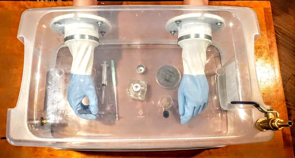
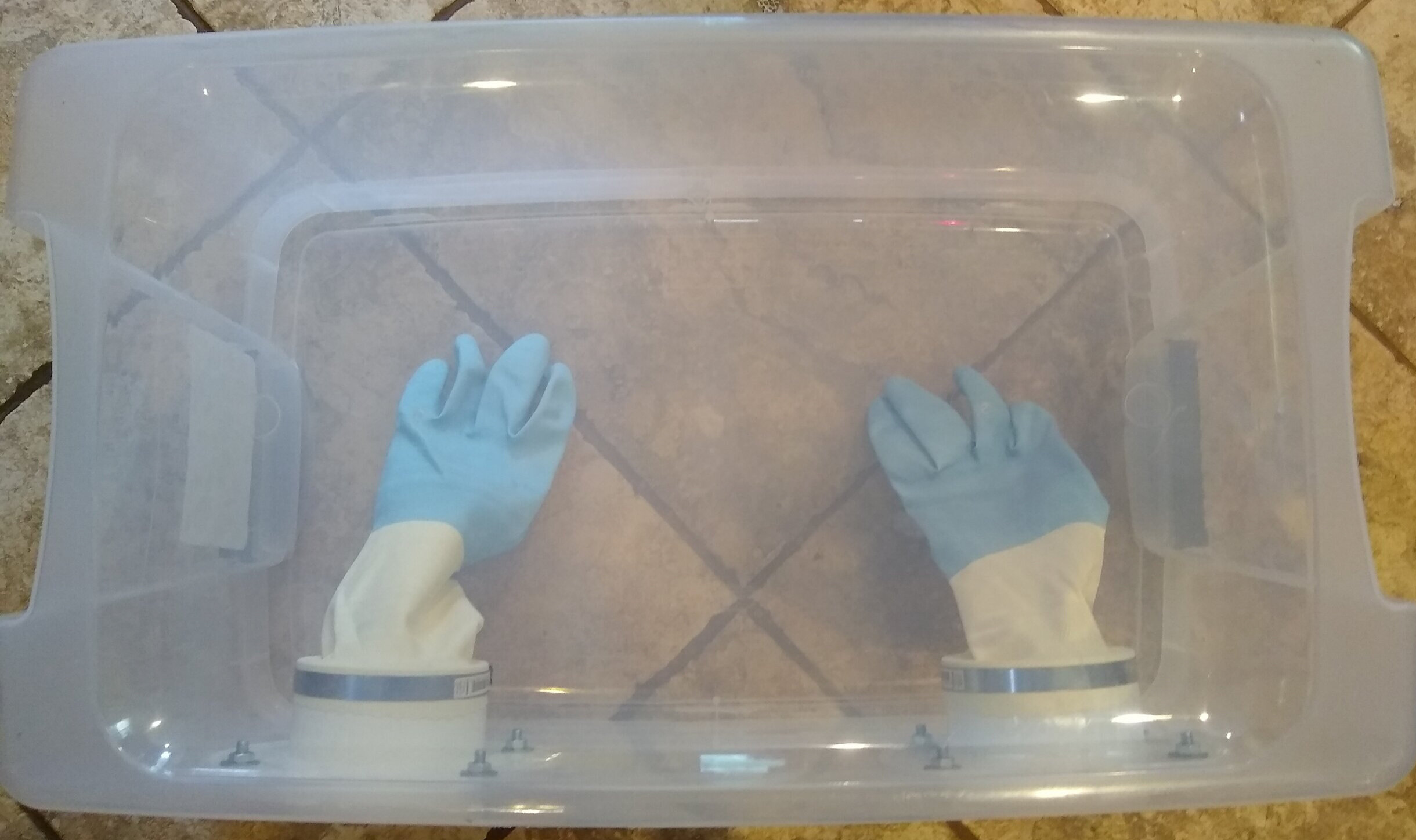
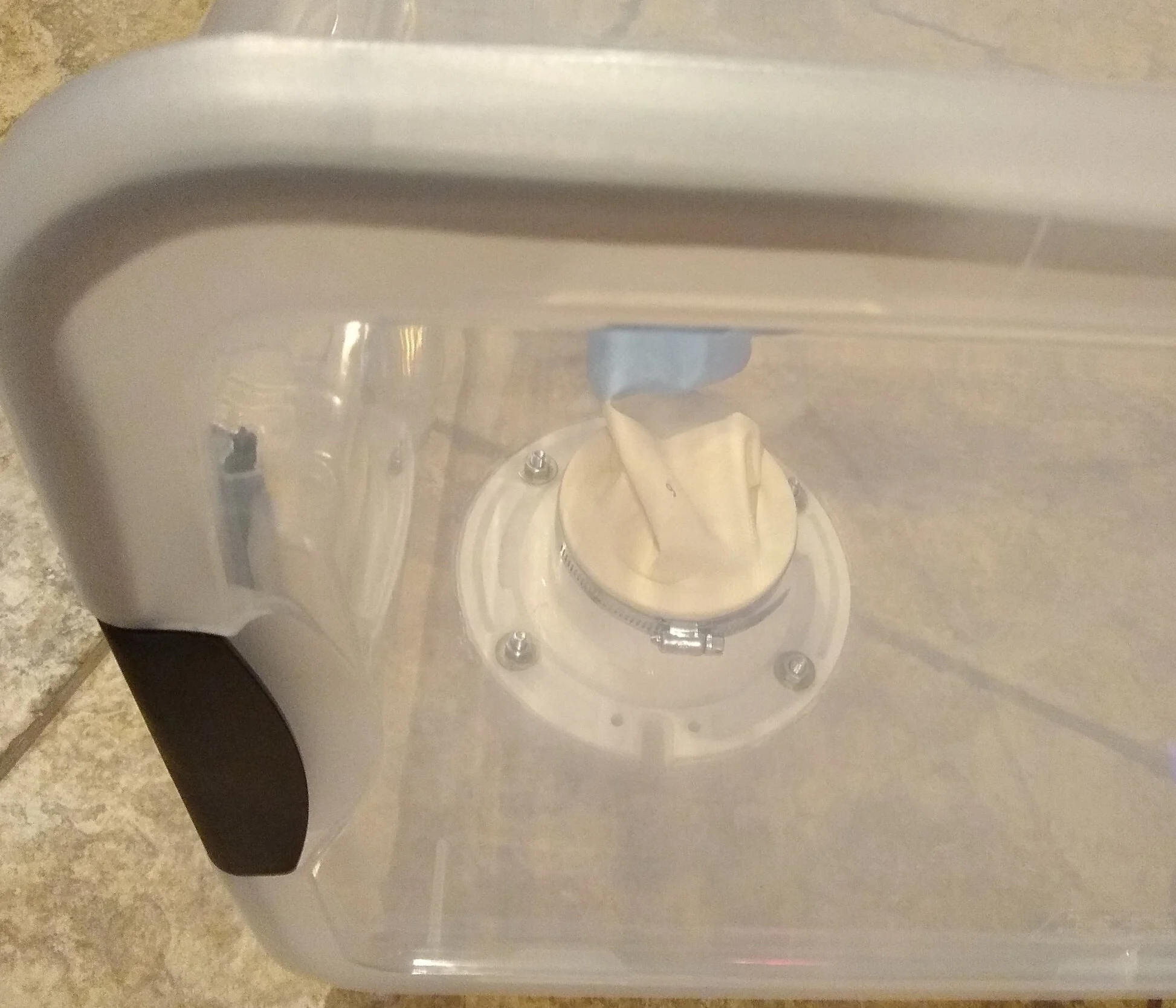
Once the PVC flanges are properly bound to the walls of the tote bin and sealed with silicone sealant, the gloves can be added. It is important that the gloves chosen for the still air box are long enough to be used to reach all areas inside the glove box and are chemical resistant, durable, and easy to clean/sterilize. It is important that the materials the gloves are made of are not too thick or rigid, as it will lower dexterity and the ability to handle small tools like scalpels, syringes, tweezers, pipettes, etc. in a proper manor. The gloves chosen were Clorox Premium Choice Gloves, which are 13” long and coated in neoprene for chemical resistance. These gloves have a relatively balanced thickness and allow unrestricted movement of the hand for complex manipulations. The gloves also have no holes or porous areas where air transfer or gaseous diffusion can take place and are relatively smooth and lack grooves or crevices, where bacteria can colonize and evade sanitation attempts. To install the gloves, first you must decide which side of the tote bin will be the bottom or working surface. For this tote bin, the top (detachable lid) is flatter than the bottom, therefore it will be designated the bottom of the still air box. Utilizing the flatter surface will mitigate the risk of graduated cylinders, vials, alcohol lamps, and Petri dishes from tipping over or spilling while working in the still air box. Since the lid of the tote bin will be used as the bottom or working surface, the gloves will be installed upside down, with the inside of the palm facing towards the lid and with the glove thumbs facing inward. First, make sure to clean any excess or unwanted silicone or epoxy off the circular flange tube inside the still air box that may have been smeared or spread to an unwanted area. Place the 4” diameter adjustable pipe clamps around the PVC flange inside the box, with the screws facing inward to allow for tightening with a screwdriver or tool, as placing them facing the walls will limit the space in which a tool can be used to tighten them. Remove any plastic tags or bar codes with warm water and a sponge, then wipe down with isopropyl alcohol or any other suitable solvent to clean the clamps and remove any residual adhesive. Carefully place the opening of the gloves over the end of the flange in the proper orientation relative to the designated bottom work area of the still air box. make sure the opening of the gloves are properly secured around the flange, with enough of the glove opening evenly stretched around the flange to ensure it will stay securely on the flange, but not overly stretched along the flange as to reduce the length of the glove and therefore limit their mobility and the ability to reach all areas inside the box comfortably. Once the proper balance between securing the glove over the flange and not limiting its working effective length is reached, place the 4” adjustable clamps near the end of the flange, over the area where the gloves are stretched onto the flange, and begin hand tightening to get near the proper diameter to fit the flange and glove. Double check that the glove is placed in the proper orientation and adjust as needed before tightening the adjustable clamp with a screwdriver, so that thee glove is tightly secured onto the flange, but be careful not to over tighten and potentially damage the gloves. Once secured, place the lid on the tote bin and place your hands in the glove ports and move them around to make sure that the gloves can reach all areas of the still air box with ease and adjust if necessary.


Now that the glove ports are installed and air-tight, the lid will need to be modified to ensure an air-tight seal. If one purchases a tote bin which already has a “weather tight” foam liner and is confident that the tote bin seals adequately, this step is not necessary. Three sizes of foam window seal/weather stripping was purchased to find the best size to seal the lid of this specific tote bin. After experimenting with the different sizes, it was found that the smallest size foam window seal (3/16” x 3/8” x 17’) worked the best to adequately seal the lid of the tote bin. The type and size of of foam window seal or similar material needed may vary depending on the specific tote bin chosen for this project. It was found that the most effective and easiest place to put the foam window seal was with the adhesive side on the rim of the lid of the tote bin. Foam window sealant was placed on each side of the rim of tote bin individually by carefully unrolling the foam window seal and slowly placing it along the edge of the lid, with the inside wall of the tote bin flush with the side of the foam seal. Make sure not to stretch the foam seal when placing it on the rim of the tote bin, as it may stress the adhesive and cause the foam seal to unravel near the corners of the tote bin where the foam seal must be somewhat curved. Stretching the foal seal while placing it will also give the impression that the foam seal can be cut shorter than needed. Make sure to keep a few extra inches of foam seal on each side, so that there is extra material available if the foam window seal does not stick/seal properly when placing the lid on the tote bin and securing the locking handle grips. Carefully place the foam window seal on each side of the rim of the tote bin once the proper size and angle of placement is found and cut the ends, still leaving a few inches of slack just in case. Ensure that the adhesive on the window seal is properly sticking to the rim of the tote bin by carefully running your fingers along the sealant, applying light pressure towards the plastic rim. Carefully and slowly place the lid on the tote bin and put the locking handle grips in place to seal the lid. Since the lid is the bottom/working area of the still air box for this tote bin, the bin is placed upside down with the lid on a flat, stable surface. Light pressure is applied to the top of the tote bin evenly and the area where the foam window seal was applied is observed to ensure the area is sealed and if the foam distorts or moves under the pressure. Adjust the placement of the foam window seal if necessary and cut the slack on the ends of the foam to fit the rim of the lid with a razor blade or scissors. During this process, two types of glues were experimented with to see if they could provide a permanent bond between the plastic lid and foam window seal without success. It was decided to just leave the foam seal as is, using the provided adhesive of the material. The foam window seal is delicate and can become detached if the foam seal is handled or stressed excessively. The same procedure for measuring and applying the foam window seal to the areas of the rim of the tote bin where the locking handle grips are located was used independently for both ends of the tote bin. Make sure to leave extra foam window seal on each side and gently apply pressure to get the adhesive to stick firmly. Carefully place the lid on the bin and seal it with the locking handle grips, then apply some pressure with the lid on a flat, even surface to make sure the foam window seal is seated properly and adequately seals the lid. Adjust if necessary and cut the extra foam off each side of the foam seal if it is placed properly. This step is very tedious and window foam size, type, and placement may vary depending on the specific tote bin used. Seal the lid by securing the locking handle grips and experiment with the still air box to make sure everything functions properly.


Congratulations, you now have a still air box that is adequate for aseptic laboratory manipulations.


Optional addition of vacuum outlet and inert gas inlet valves to make a still air box/glove box combination:
This next section is optional and will outline the materials and instructions for installing a vacuum outlet valve and inert gas inlet valve to make a still air box/glove box combination for handling air-sensitive chemicals. The vacuum outlet can be utilized to purge the atmosphere inside of the glove box using a vacuum pump, with the vacuum outlet open while keeping the inert gas inlet closed. The inert gas (generally nitrogen or argon gas; argon is preferred for working with many main group elements and alkali earth elements, such as elemental calcium, as nitrogen reacts with elemental calcium to form calcium nitride) is then carefully used to fill the space inside the glove box. Purging the atmosphere inside the glove box with vacuum and flushing it with an inert gas is generally carried out as outlined above three times sequentially. This procedure ensures the space inside the glove box is filled with only the inert gas and there is as little oxygen present as possible. Simply adding nitrogen gas to the glove box with a vent to the atmosphere will work, but the inert gas will diffuse and mix with the oxygen inside the glove box and only slowly lower the concentration of oxygen in the glove box. To achieve a truly inert atmosphere in the glove box without utilizing a vacuum pump will take an excessive amount of time and inert gas, which is inefficient. Therefore, vacuum is used in conjunction to first remove the oxygen in the glove box so when the inert gas is added, the space inside the glove box is essentially free of oxygen and can be filled with only inert gas. Alternating between vacuum purging and flushing with an inert gas three times will remove almost all oxygen content in the glove box, creating an optimal environment for working with sensitive compounds.
This project will utilize two 1/4” lead free brass ball valve female NPT x female NPT, four 1/2” SAE flat washers hardened, two (12.37 x 2.62mm) viton o-rings, two 1/4” MIP x 1/4” MIP hex nipples, two 1/4” FIP x 1/4” FIP couplings, one 1/4” ID x 1/4” MIP hose barb adapter for the inert gas inlet, and one 3/8” barb x 1/4” MIP hose barb adapter for the vacuum pump outlet (change the diameters of the hose barbs if needed to match the diameter of the vacuum pump and inert gas tank tubing for your setup, these specific diameter barbs were chosen because they fit our equipment). To begin, apply 2-3 layers of teflon tape (look online for how to properly apply it) to one side of the threading of each of the 1/4” MIP x 1/4” MIP hex nipples. Next, apply 2-3 layers of teflon tape to the threading on each of the hose bard adapters. Screw the hose barb adapters into the respective ball valves on the side of the ball valve where the handle is located when the valve is opened. This ensures that the ball valves can be opened and closed without the walls of the glove box being an obstruction. Then screw the teflon tape coated end of each of the 1/4” MIP x 1/4” MIP hex nipples into the ball valves. Hand tighten everything at first and once they are correctly installed, tighten with the proper wrench to make sure they are sealed tightly. For each ball valve, place a 1/2” SAE flat washers on each of the free threaded ends of the 1/4” MIP x 1/4” MIP hex nipples, followed by the appropriate sized viton o-ring, then another 1/2” SAE flat washer, and finally screw on the 1/4” FIP x 1/4” FIP coupling lightly to make sure everything fits properly. This is the order in which the washers, o-rings, and couplings on the ball valves will be installed so that the ball valves can be sealed to the walls of the glove box. The viton o-rings are placed on the outside surface of the wall of the glove box to create an air-tight seal, while the second washer and 1/4” FIP x 1/4” FIP coupling will be inside of the walls of the glove box. The internal washer will help to create more surface area in contact between the plastic wall and the ball valve to prevent the plastic from cracking or warping/twisting when the ball valve handles are closed and opened.


The final steps are to drill holes for the vacuum outlet and inert gas inlet valves. The placement of the valves are up the the user and dependent on the shape of the tote bin. For this project, the inert gas inlet valve was placed on the right side of the tote bin, in the bottom right quadrant (when the tote bin is upside down and glove box holes are facing nearest to the user). The inlet valve was placed near the bottom of the tote bin because nitrogen gas will be used as the inert gas. In this configuration, the gas can enter the bottom of the box and push the oxygen upwards, as nitrogen gas is slightly lighter than oxygen and will otherwise not flush out the box efficiently if the inlet valve is placed near the top of the box. The vacuum outlet valve was placed on the top, in the back left quadrant of the glove box (when the tote bin is upside down and glove box holes are facing nearest to the user). This was the chosen position of the vacuum outlet because the area that it was placed in had thick, flat plastic. The area was also on the other side of the box from the inert gas inlet (to encourage diffusion when flushing the box), and was in a convenient position to connect to the vacuum pump setup. The areas you chose to place your valves may vary and are specific to the box or material being used. A 1/4” drill bit was used to drill the holes for both valves in the specified areas. The inert gas inlet valve was placed approximately 4” from the bottom of the box when in the functional position, in the center of the back right quadrant. The vacuum outlet hole was drilled in the above mentioned area, where the plastic walls were thick and flat to prevent warping or torsion when opening the valve. Both holes were then lightly filed to remove burrs and gently sanded. Both hex nipple threaded ends installed on the ball valves were placed through the holes with the 1/2” washer and viton o-ring on the outside of the box. The second 1/2” washer was placed on the hex nipple threading inside of the box, followed by the 1/4” FIP x 1/4” FIP coupling. The coupling was hand tightened for each valve and double checked to ensure it was assembled correctly, then tightened with the proper wrench. The inlet valves should now be air tight, stiff, and not cause torsion of the plastic walls of the box when the ball valves are opened and closed. The only problem with this tote box is that the locking handle grips have small open gaps between them and the plastic box to allow them to rotate, therefore they will need to be sealed before being able to use the box as a glove box. If not sealed, vacuum purging will bring oxygen from the the outside atmosphere into the glove box and the inert gas will slowly leak out once it has filled the area in the box. Make sure to buy the proper tote bin or box and inspect it for any holes or potential problem areas before purchasing it.


Commentary and extension:
Using a tote bin to create a still air box/glove box combination is a cheap and easy way for the amateur scientist to begin learning microbiology and chemistry laboratory manipulations. The design is simple and very easy to assemble yourself with minimal tools in a short period of time. This configuration can be improved on in a number of ways to make the still air box more effective and easier to use:
Install a HEPA air filter to create positive pressure in the system and bring in a constant stream of clean air into the box to achieve laminar flow.
Install an automated UV light inside the box for timed decontamination cycles prior to use. This will improve the sterility of the still air box.
Create a stand for the still air box and make the base of the stand into the working area to replace the lid as the working area, using inert and strong plastic materials. A small antechamber can be created to place objects inside the still air box without having to disassemble it.
A simple hinged port cover can be created on the side or top of the still air box to bring objects inside of it without having to disassemble it.
Install a shelf inside the still air box to allow certain items to remain secured in the still air box for extended periods of time.
In the future, we will probably build a more advanced still air box or glove box for permanent usage made from plexiglass. Thanks for checking out our first tutorial blog post, we are very excited to bring you more scientific content in the future. If you would like to see any specific tutorials or projects done in the future, please like and comment or email us.