
How to Build a Dual Water Aspirator Vacuum Pump/Circulating Water pump

Overview and scope:
This tutorial will show you how to create a cheap water aspirator vacuum pump with the option of utilizing the circulating water to create a circulating water pump to provide cold water flow to condensers for chemistry procedures. The main goal of this tutorial is to showcase an alternative way to obtain moderate vacuum capabilities without having to purchase an expensive vacuum pump. The utilization of vacuum is essential in the field of chemistry, as it can be used to boil solvents at lower temperatures during distillation, to perform vacuum filtration, and to carry out many other procedures. This project utilizes two main devices: a water aspirator and a 12V DC diaphragm water pump. The water pump provides a rapid flow of water through the water aspirator and utilizes the Venturi effect to create vacuum. One can simply connect the two devices and allow indirect re-circulation between the devices via a water reservoir to achieve moderate vacuum. Furthermore, the outlet water flow from the water aspirator can be channeled to provide a source of cold water flow for condensers and other apparatuses. As long as the outlet from the condensing apparatus is redirected back into the main water reservoir, so that the water level in the water reservoir is maintained, the pump can continuously suck up water so that it will not run dry. Simply put, we can recycle the water and utilize the system for multiple purposes at once. Typically, water aspirators are connected directly to a laboratory faucet (or any faucet) with running water going through the aspirator to create a vacuum. The outlet water of the aspirator usually goes directly into the sink and any noxious vapors taken in from the vacuum will mix with the water and also go into the sink, which can contaminate the main water source. The method used in this procedure will not contaminate the main water source of the facility it is being used in because the water is recycled. The water reservoir can be modified with specific chemicals to neutralize any noxious vapors or chemicals brought into the water reservoir, depending on the procedure being carried out.


Parts list:
bayite 12V DC Fresh Water Pump with 2 Hose Clamps 12 Volt Diaphragm Pump Self Priming Sprayer Pump with Pressure Switch 4.5 L/Min 1.2 GPM 80 PSI Adjustable for RV Camper Marine Boat Lawn (can choose any similar pump that will work, but note voltage, amperage, wattage, and flow rate to correctly assemble the circuit)-purchased from Amazon.com
Nalgene 6140-0010 Faucet Aspirator Vacuum Pump (or any suitable water aspirator)
ProLine Brass 3/8” barb x 3/8” FIP adapter
1 x 3/4” brass pipe screen
1 x Nylon 3/8” barb x 3/8” FIP adapter
1 x Nylon 3/8” hose barb x 3/8” hose barb elbow
8 x #4 hose clamps (~7/32”-5/8”)
4 x Hex Cap Screws, Class 8.8, M6-1.00 x 20
4 x Insert Lock Nuts, Nylon Class 8, M6-1.00
8 x Flat Washers, 6mm
10’ Air Hose, 3/8” ID, 5/8” OD (purchased extra just in case)
20’ PVC Tubing, 3/8” ID, 1/2” OD (purchased extra just in case)
12V DC power supply/source
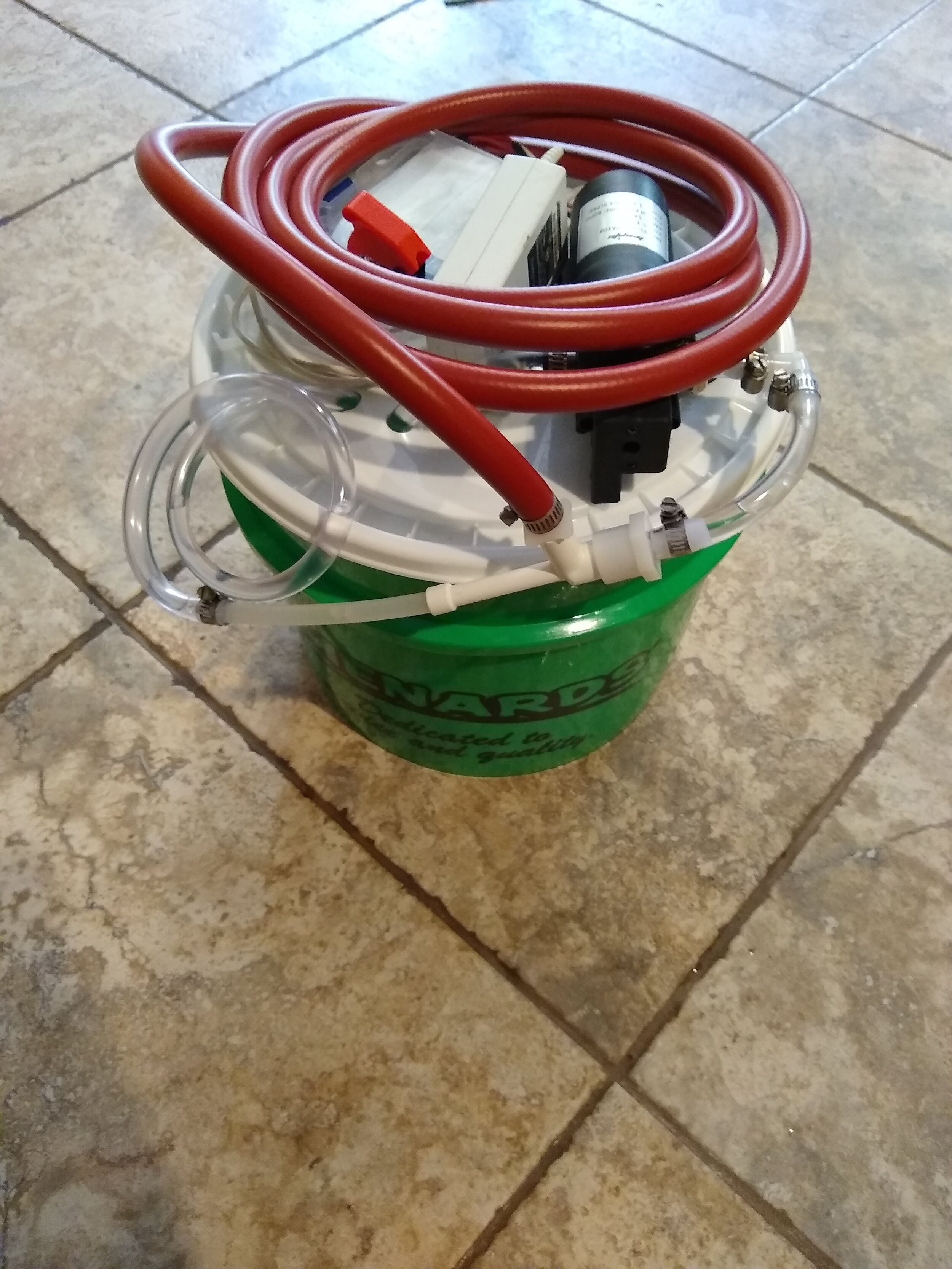
Bucket (preferably with a flat lid)
miscellaneous electronics to create a circuit for the power supply, corresponding to the electronic requirements of the water pump (switch, wires, heat sink, blank circuit board, resistors, project box, etc.)


Instructions:
General assembly of water the pump and aspirator onto the water reservoir:
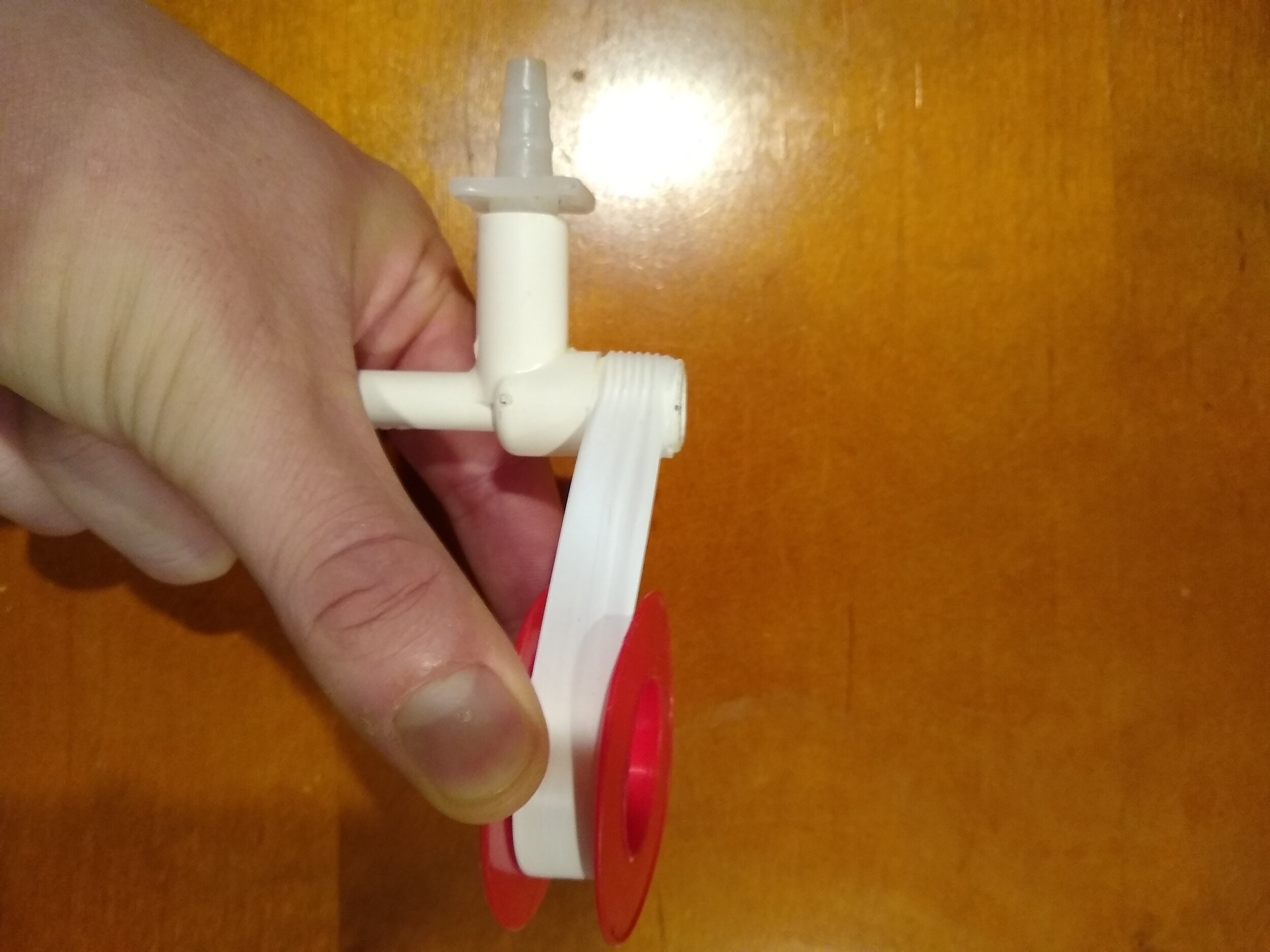
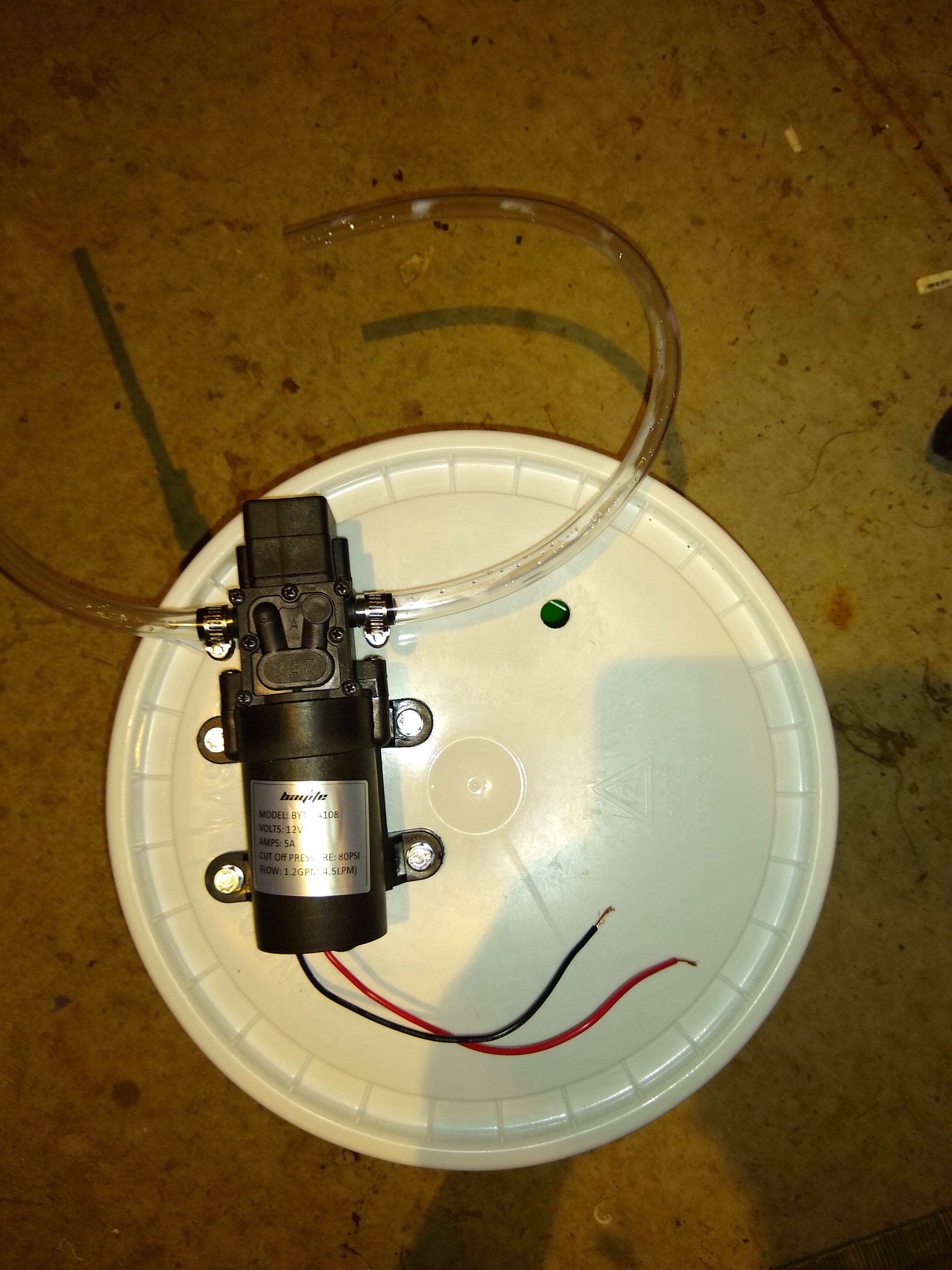
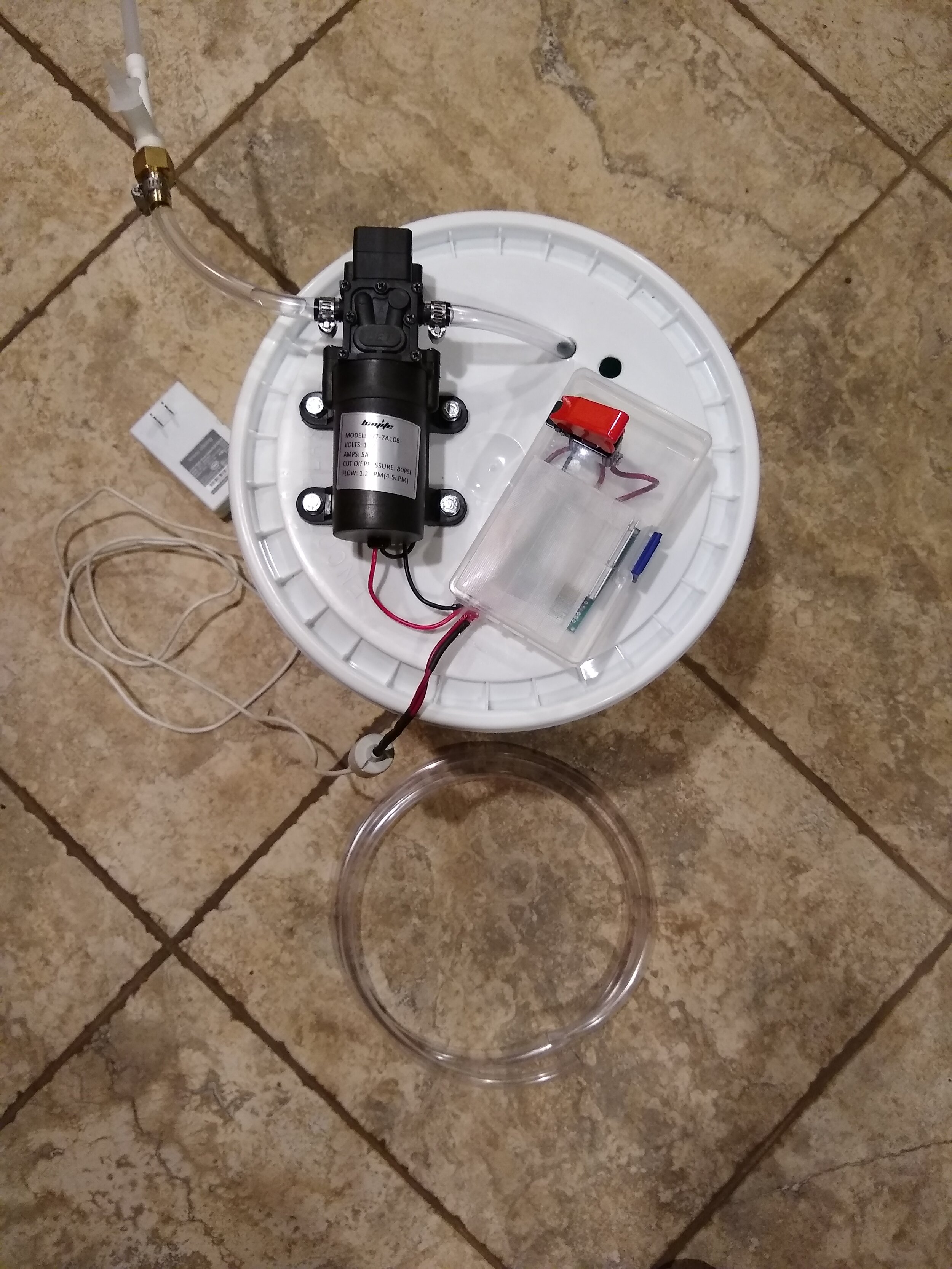
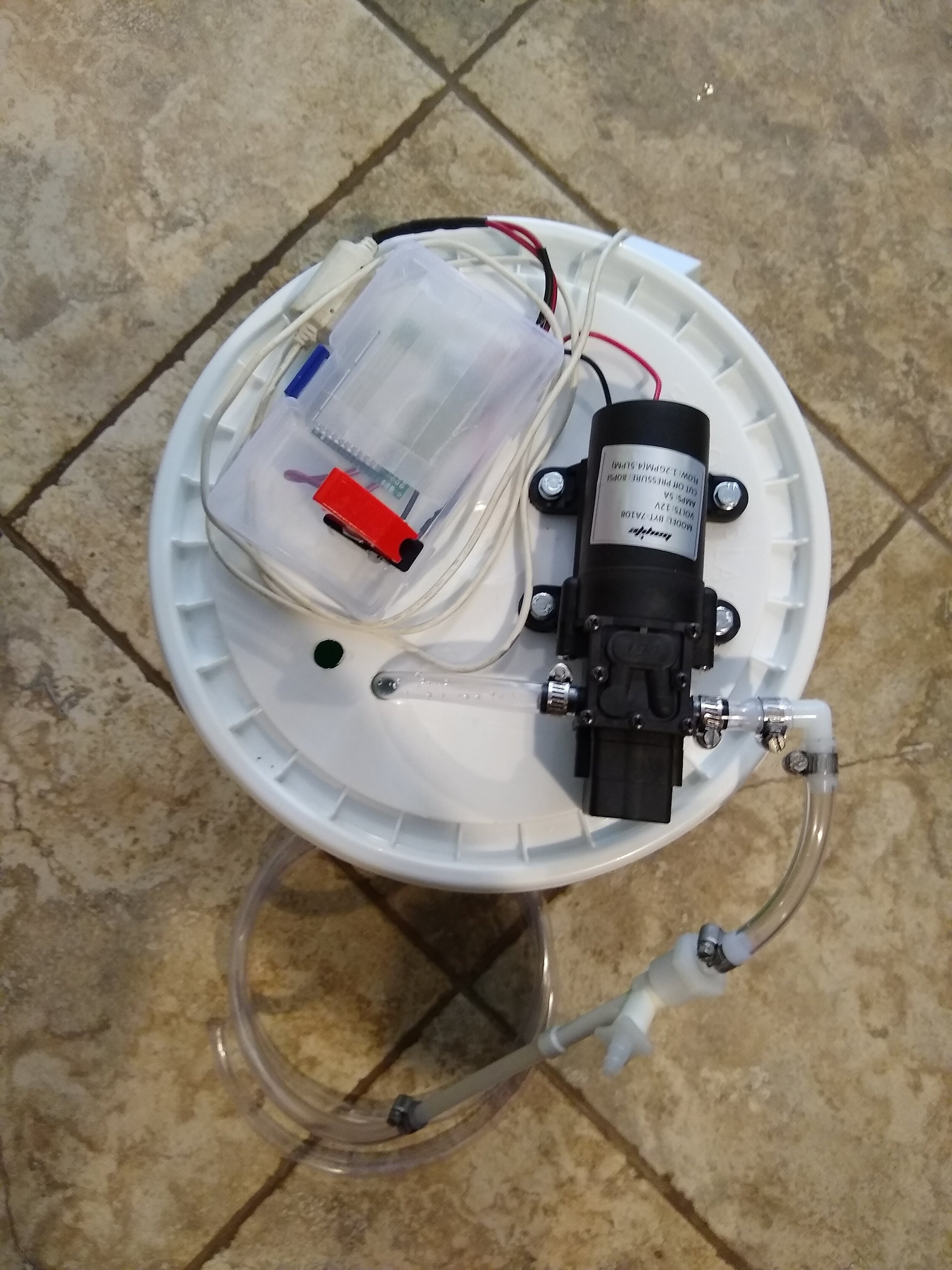
Find a reservoir or bucket that will be able to hold a few gallons of water with a relatively flat lid. In this case, a smaller bucket was chosen for portability. Begin by wrapping the water aspirator threading with 2-3 layers of Teflon tape to ensure a proper seal. Screw on the Nylon 3/8” barb x 3/8” FIP adapter tightly. Note: initially a brass barb adapter was installed on the water aspirator, but was changed to nylon to prevent stripping of the threading of the water aspirator. Disregard any pictures which show the brass barb adapter on the water aspirator.

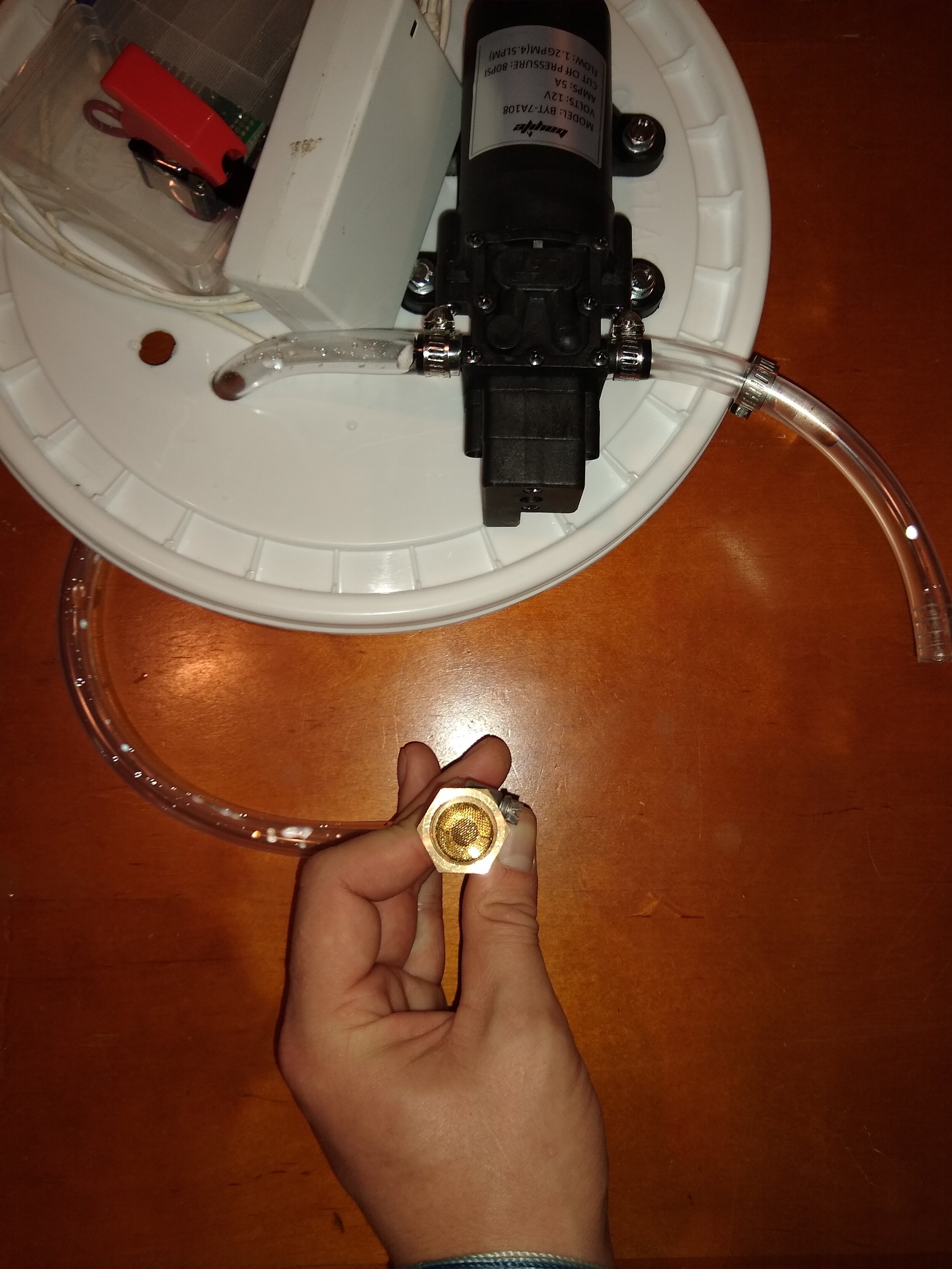
Next, cut an 18” long section of the 3/8” ID, 1/2” OD PVC tubing (change length depending on water reservoir chosen) and ensure that the tubing is long enough to reach the bottom of the reservoir from the the inlet of the water pump where it will be mounted. Place the tubing over the water pump inlet and place the hose clamp on the barb and tighten it to secure the connection. Take the 3/4” brass pipe screen and carefully place it into the brass 3/8” barb x 3/8” FIP adapter. This will be used as the inlet filter to prevent particles in the water reservoir from harming the water pump.


A 6” piece of 3/8” ID, 1/2” OD PVC tubing was placed over the water pump outlet and secured with a hose clamp. The water aspirator was added to the other end of the 6” tubing and secured with a hose clamp to temporarily test if the vacuum pump worked. The hex cap screws, flat washers, and insert lock nuts were assembled with two washers on each screw. One washer will be on each side of the lid of the bucket when assembled. The water pump was placed on the lid to find a suitable position for mounting, and the screw holes were marked with a pen. Four holes were drilled in the marked locations on the lid of the bucket for mounting the pump. The pump was then placed into position and secured to the lid of the bucket with the hex cap screws. A hole was drilled next to the water inlet of the pump and the inlet tubing was placed through the hole. The water inlet tubing should comfortable reach the bottom of the reservoir and have a few extra inches of length, so that the pump will always have access to water and not run dry.


Overview of assembly of power supply:
This section will not going into much detail about the assembly and specifics of the power supply because many 12V DC water pumps have different electrical requirements and their respective power supply can be configured in a myriad of ways. The water pump used in this project required a 12V DC power source with a required minimum of 5 amps (water flow rate of 4.5 L/Min, 1.2 GPM, 80 PSI adjustable). A 120V AC input/12V DC output power supply recycled from a scrapped electronic device was used to supply the power. A PCB, two 10 ohm resistors, and an aluminum heat sink were soldered together to provide the correct power requirements for the water pump. A hobby box was used to house the switch and circuit. A small rectangular opening was cut out of the hobby box with a razor blade to allow for air cooling of the resistors.


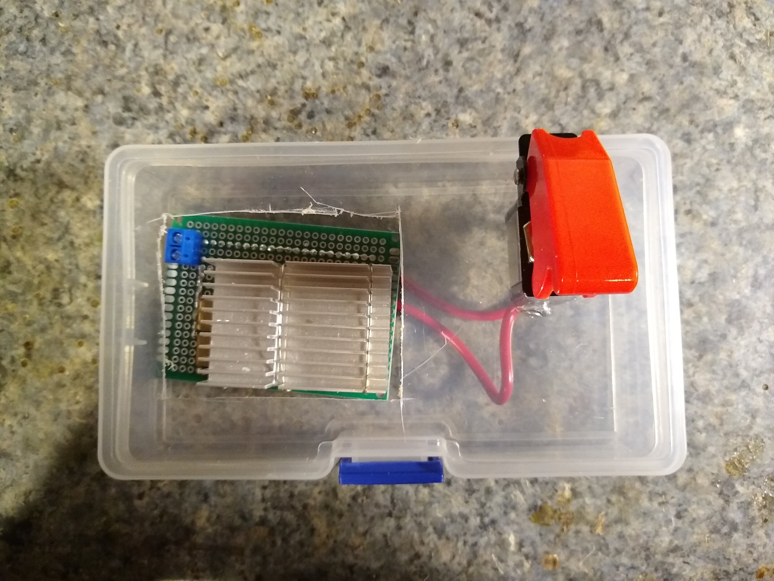
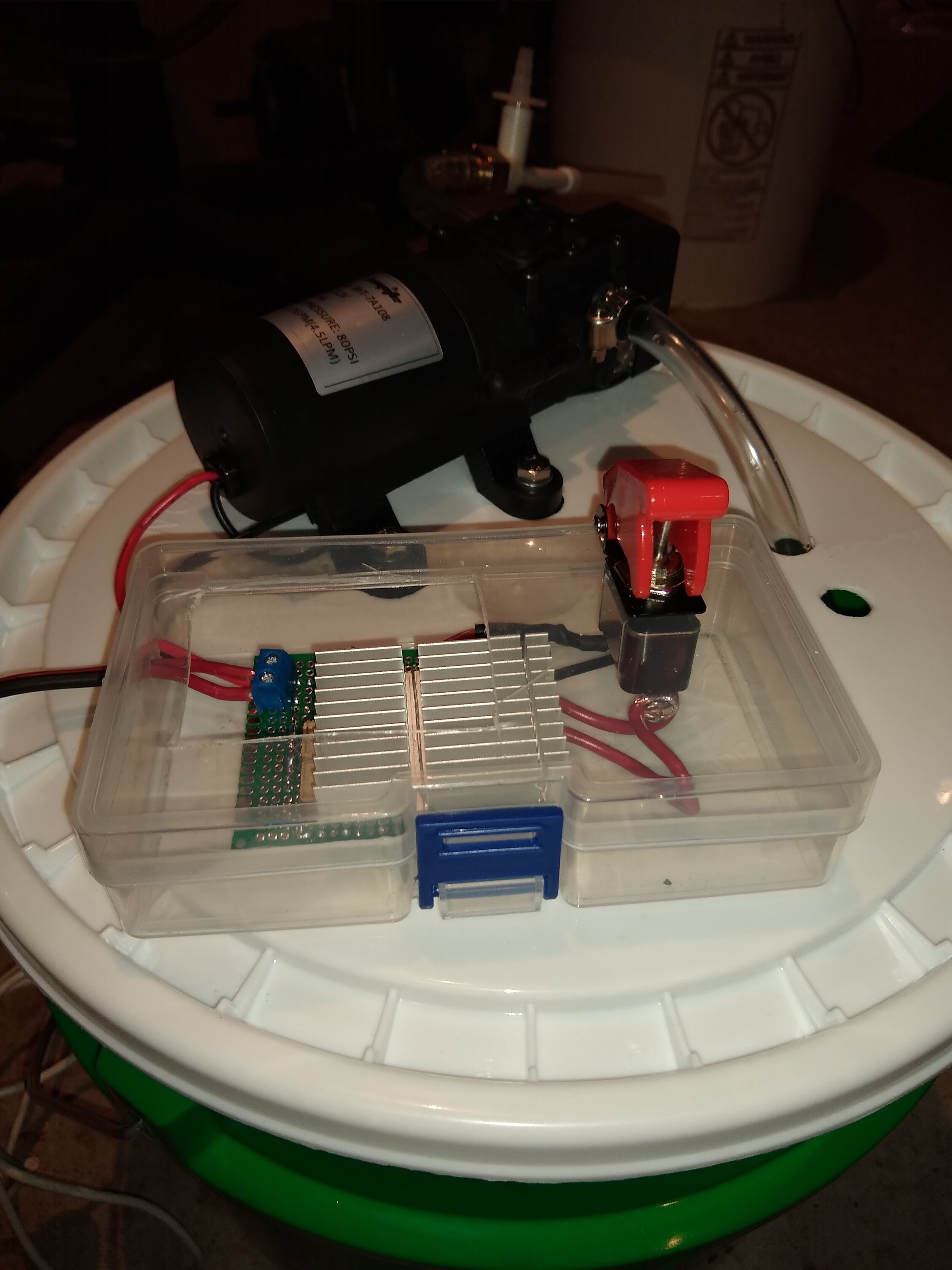
Once the circuit was assembled and housed in the hobby box, it was placed on the top of the bucket and hot glued in the chosen location. The opening in the hobby box was covered with micro-pore tape to prevent water from contacting the electronic parts and to allow air exchange for cooling. After the electronics were mounted to the lid of the bucket, a second hole for the water outlet was drilled in the lid, right next to the water inlet hole.


Initial test and final changes to the tubing configuration:
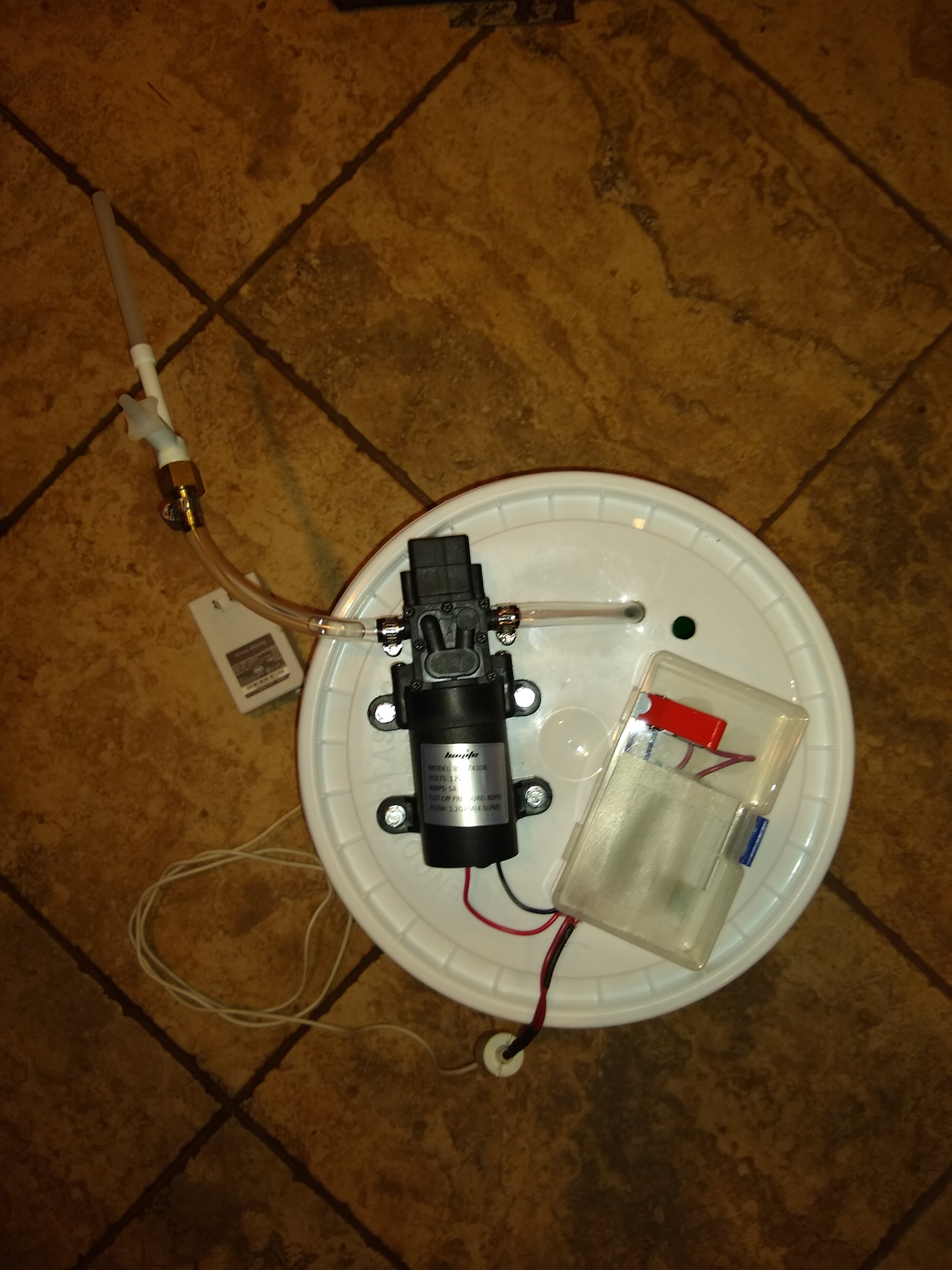
A 5’ piece of 3/8” ID, 1/2” OD PVC tubing was placed onto the outlet of the water aspirator and secured with a hose clamp. This was placed into the second hole drilled for the water outlet. The bucket was filled with water and the power source was plugged into the wall outlet for testing and successfully pulled moderate vacuum. The water outlet was disassembled to change the configuration of the tubing. Meanwhile, the previously made brass 3/8” barb x 3/8” FIP adapter with brass filter was secured to the end of the water inlet tubing.

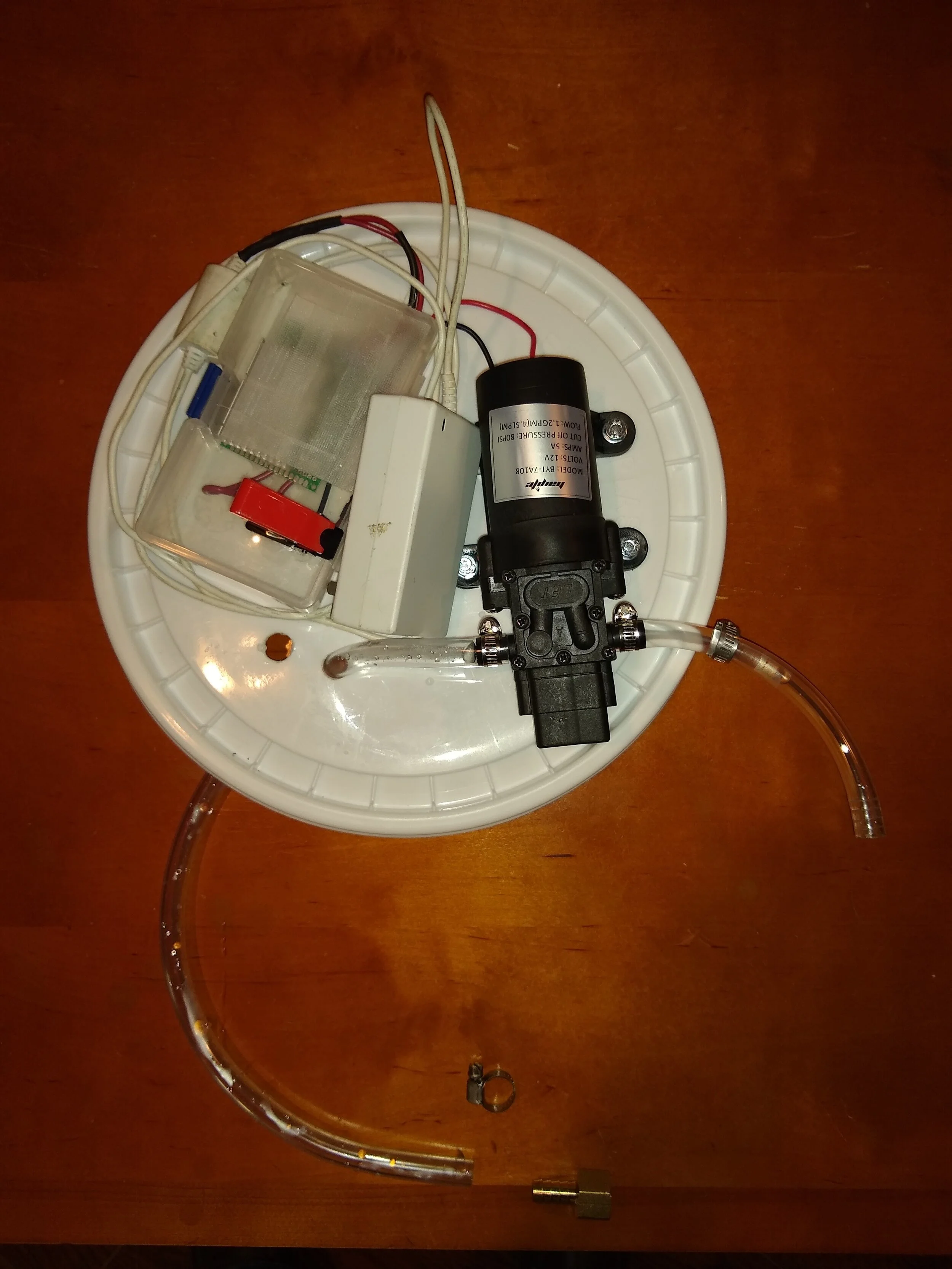
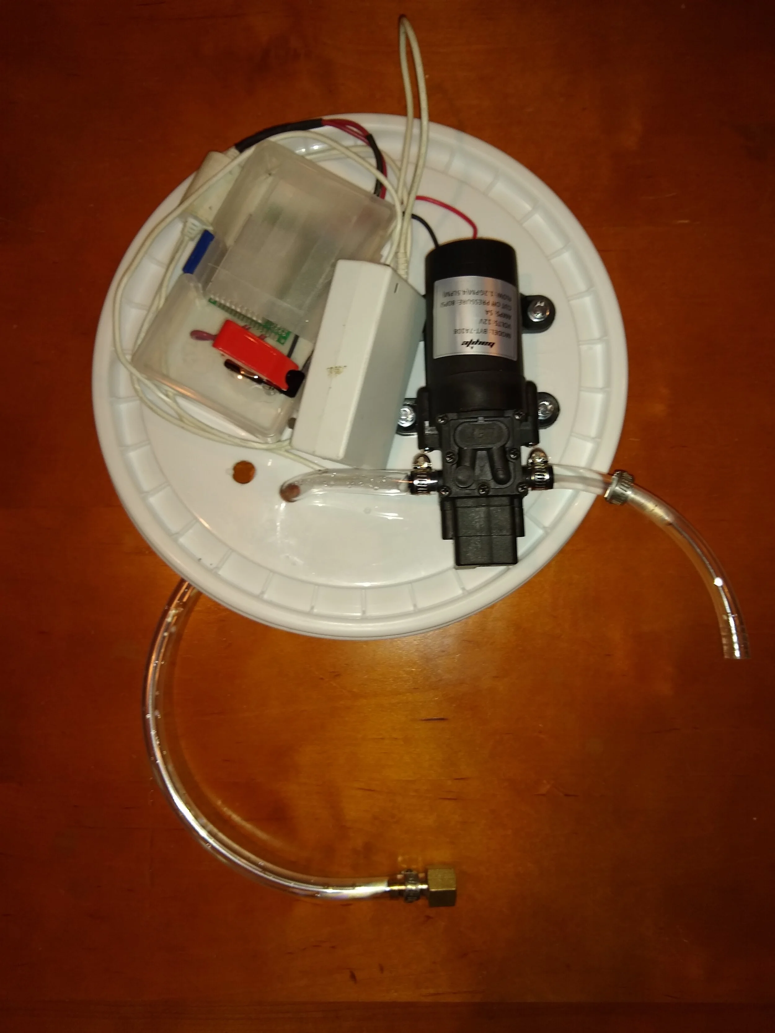
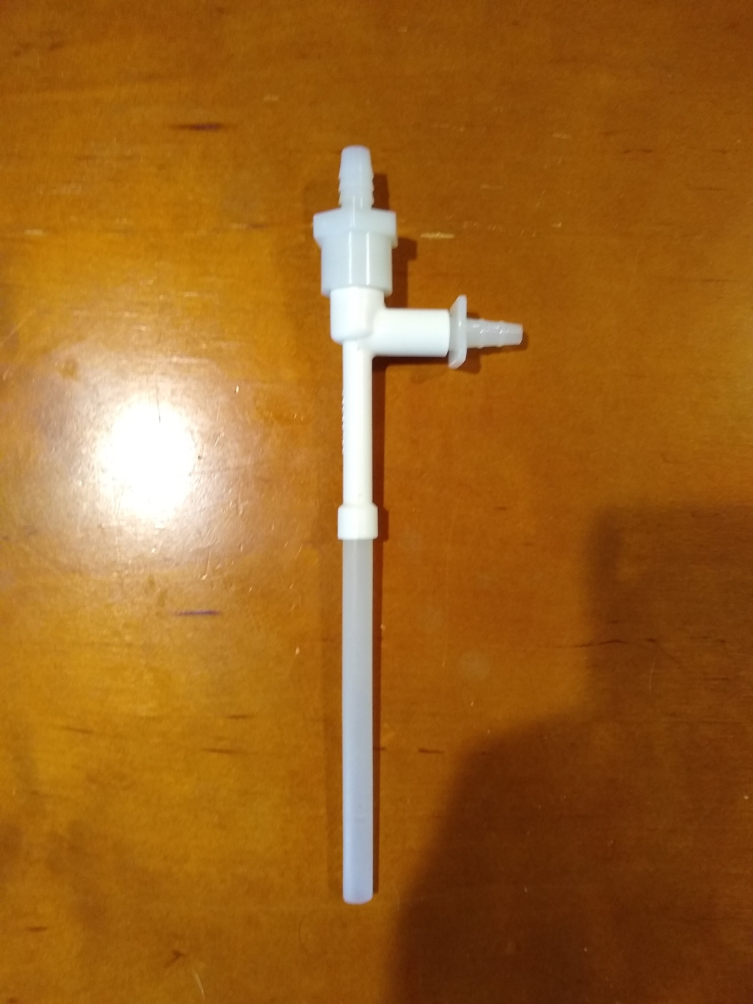
The previously used 6” segment of 3/8” ID, 1/2” OD PVC tubing was cut into two segments of 1.5” and 4.5” length. The 1.5” segment of tubing was attached onto the outlet barb of the water pump followed by the nylon 3/8” hose barb x 3/8” hose barb elbow, and both were secured with a hose clamp. The 4.5” segment of tubing was connected to the other end of the nylon 3/8” hose barb x 3/8” hose barb elbow followed by the barb of the nylon 3/8” barb x 3/8” FIP adapter connected to water aspirator. Both sections were secured with hose clamps. The previously cut 5’ segment of 3/8” ID, 1/2” OD PVC tubing was attached to the outlet of the water aspirator and secured with a hose clamp. The tubing was fed into the water outlet hole in the lid of the bucket.


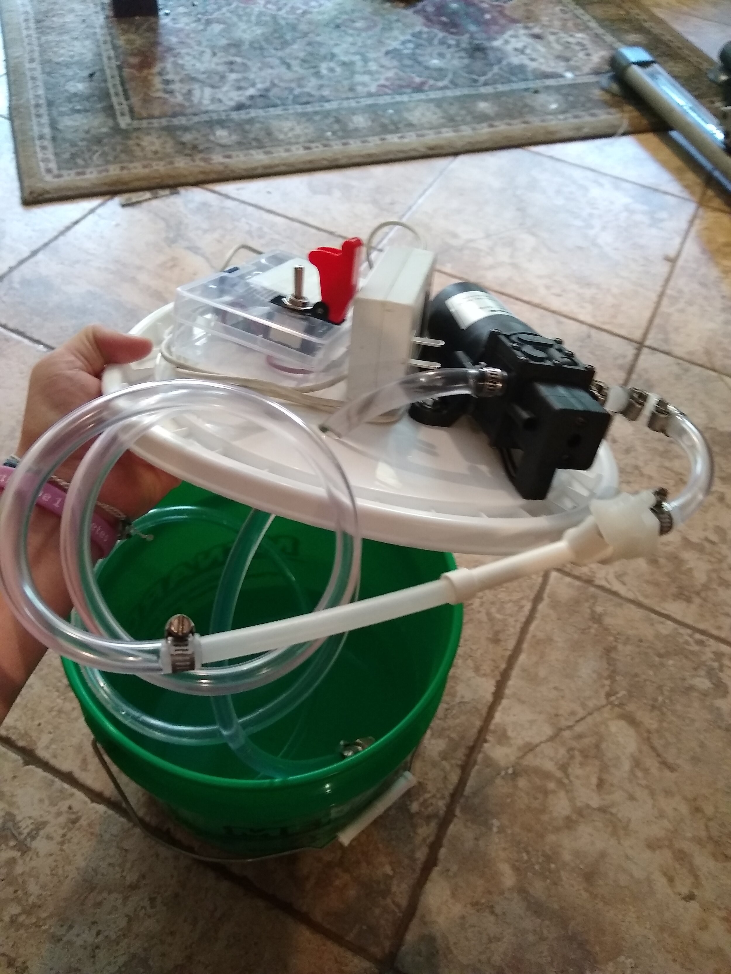
The apparatus is now complete. The 10’ length of 3/8” ID, 5/8” OD air hose was secured to the vacuum inlet of the water aspirator. This gave an ample length of tubing to connect to any apparatus that requires vacuum. The vacuum strength is moderate and adequate for most purposes.


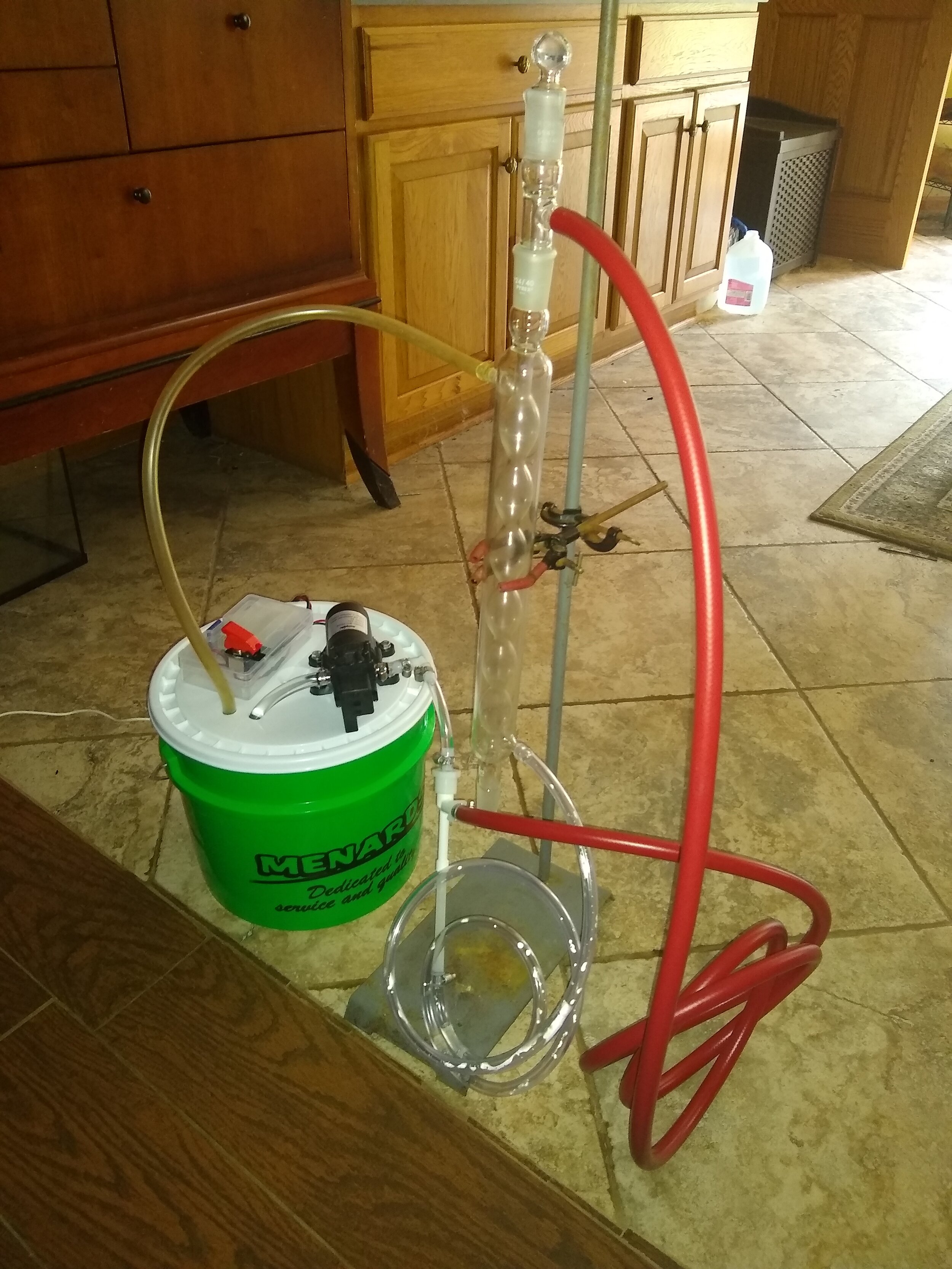
Use as a dual water aspirator vacuum pump/circulating water pump:
The circulating water of the water aspirator vacuum pump can be utilized to provide circulating cold water to a condenser or other apparatus. Using the circulating water to cool a condenser will lower the vacuum strength somewhat, as the water pressure will be lowered. When configured solely as a water aspirator vacuum pump, an average vacuum strength of 460 mm Hg (+/- 2% error) was achieved with a maximum vacuum strength of 480 mm Hg (+/- 2% error). The Nalgene 6140-0010 Faucet Aspirator Vacuum Pump used for this apparatus states an ultimate achievable vacuum strength of 724 mm Hg. The vacuum strength was lowered when configured as a dual water aspirator vacuum pump/circulating water pump and the vacuum strength varied depending on the internal volume and surface area of the apparatus that the water was circulated through. In general, the larger the area and height the water had to travel, the lower the vacuum strength.


After testing this vacuum system on a variety of applications, it was found to be reliable and no major components failed at any time. The brass screen inlet filter was required to be cleaned a few times after long use (the water flow rate significantly slowed down when particles clogged the filter) and it is important to always use clean, particle free water in this system to avoid clogging. It is also important to empty the water reservoir when not in use, as even a few days of keeping the stagnant water in the reservoir led to the formation of mold. Also, the water pump will get relatively warm after about an hour of use and it is advised to turn off the power after this time to let the pump cool down.
For many applications, it was found the dual use as a circulating water pump was not feasible, such as for providing circulating cold water for a Buchi rotary evaporator. First, the length of the dual coil condenser of the rotary evaporator slowed down the current of water flow and significantly decreased the vacuum strength. Secondly, the rapid flow of water caused the condenser coil to rattle vigorously and risked damaging the expensive equipment. In addition, the vacuum strength of the system configured only as a water aspirator vacuum pump was not strong enough to use for rotary evaporation, unless the heat of the water bath was set above 40-45°C. However, it worked perfectly for vacuum filtration and small scale vacuum distillation procedures where the apparatus had minimal inner surface area to evacuate with vacuum. In general, the use as a dual water aspirator vacuum pump and circulating water pump was very limited in its applications. This system is best used as a simple and cheap water aspirator vacuum pump for procedures requiring low-medium vacuum strength. It can only be used as a circulating water pump in a small number of applications. The main problem is that using long lengths of tubing connected to a condenser significantly slows the water flow, lowering the vacuum strength.
A recent publication related to this type of system was found independently after finishing this project and has a lot of good information about the concepts and construction of this type of system. The link to the publication can be found below.
https://pubs.acs.org/doi/full/10.1021/acs.jchemed.9b01123
Using the data in this publication, a 3-D printer was employed to create a water aspirator vacuum pump from PLA using a 0.16 mm layer height. Upon testing, this 3-D printed aspirator failed to function properly. The failure was most likely due to the layer height, as the publication uses a much smaller layer height.